
(Feature Image Modified from K. Key)
The marine controlled source electromagnetic method uses a horizontal electric bipole dipole as a transmitter. The transmitter consists of two electrodes separated between 100-300 m. The transmitter is towed 25-50 m above the seabed at a speed of 1.5 to 2.0 kn (WesternGeco, 2008). The transmitter uses a powerful source and generates around 1000 A. Two examples of transmitters are seen in Figure 1-1 and Figure 1-2. Figure 1-3 is a schematic showing the general components of an electromagnetic transmitter. There are numerous commercially available transmitters that can be selected prior to surveying.

Figure 1: Picture of a commercial transmitter (Reproduced form WesternGeco, 2008).
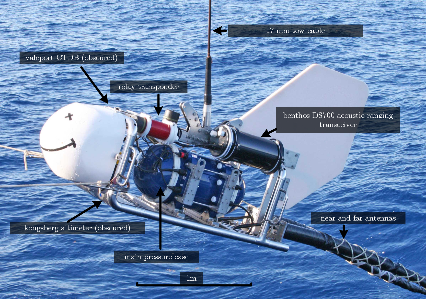
Figure 2: Annotated photograph of the Scripps undersea electromagnetic source instrument (SUESI) horizontal electric dipole source (Modified from Key, 2009)
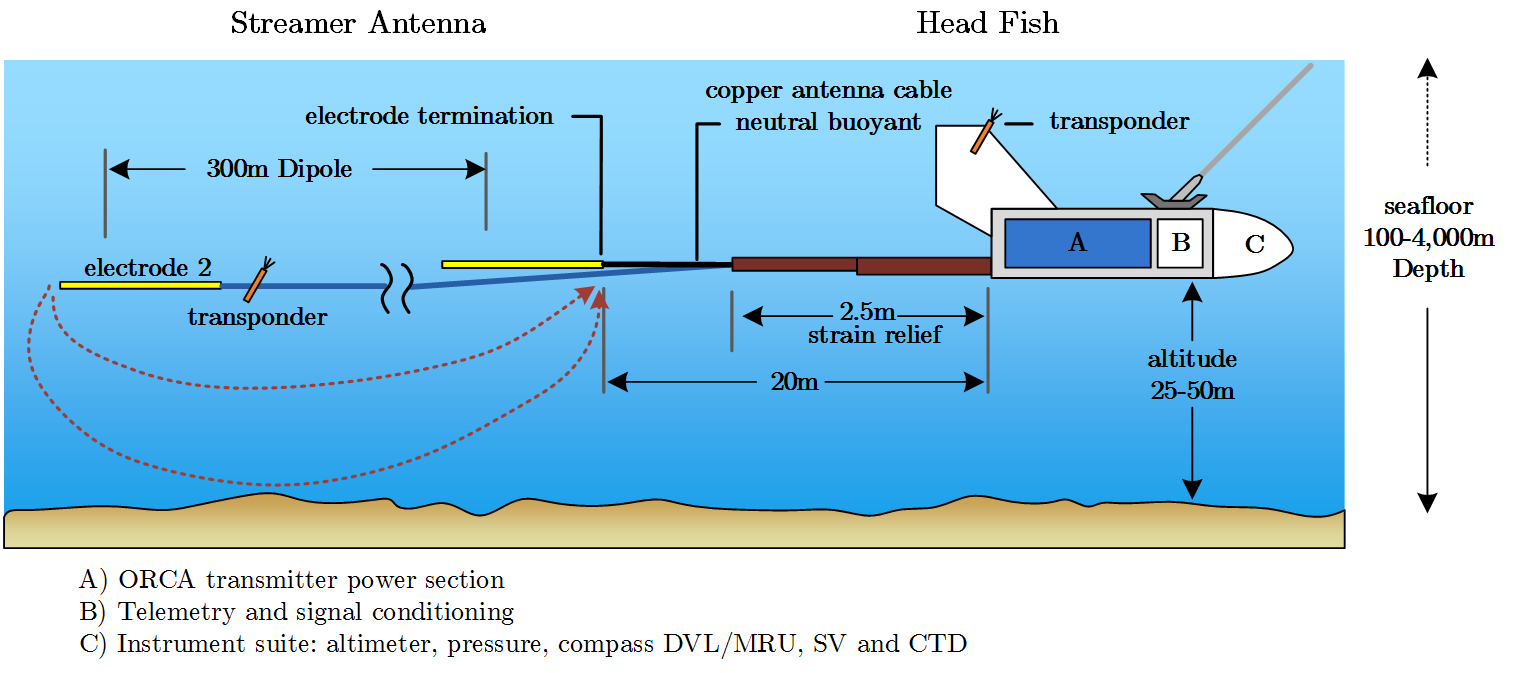
Figure 3: Typical schematic of a marine CSEM transmitter and HED (Reproduced from WesternGeco, 2008).
Features to consider when selecting a transmitter include the peak output dipole moment and the stability of the output waveform. Waveform polarity transitions have a temperature-dependent latency (1-2 ) that decreases as the transmitter temperature rises and stabilises (WesternGeco, 2008). The output waveform’s phase must be stable to around 1 part in 108 (1 ms/day) otherwise the received waveform will be artificially out of phase with the transmitted waveform. Phase is controlled by GPS and consistently monitored during the survey.
The dipole moment is the length of the electrodes multiplied by the transmitted current. If the dipole moment is doubled, the amplitude recorded at the receiver is also doubled. The source is deep-towed to optimise signal coupling with the sea floor and to reduce the conductive
losses. Heights of around 25-50 m are chosen but can be varied in accordance to bathymetry, ocean conditions and the coupling required. The altitude of the transmitter is constantly monitored by using an altimeter on the source. The tow speed of the transmitter should be considered prior to surveying as it affects the quality of the received data. A receiver records 50 transmitter cycles every 100 m for a given frequency of 0.5 Hz and a towing speed of 1 m/s. Stacking reduces the noise by a  times and improves with slower towing speeds (Hoversten et al., 2006).
References
Hoversten, G. M., F. Cassassuce, E. Gasperikova, G. A. Newman, J. Chen, Y. Rubin, Z. Hou, and D. Vasco (2006). Direct reservoir parameter estimation using joint inversion of marine seismic ava and csem data. Geophysics 71 (3), C1–C13.
Key, K. (2009). Scripps undersea electromagnetic source instrument. http://marineemlab. ucsd.edu/instruments/suesi.html.
WesternGeco (2008). Westerngeco. http://www.westerngeco.com/content/services/electromagnetic/wgem.asp?